PRODUCTS
- High Voltage Transformers
- Switchmode Transformers
- Flyback Transformers
- Trigger Pulse Transformers
- Step Up/Down Transformers
- Power Transformers
- Toroidal Transformers
- Antennas and Air Coils
- Down Hole Applications
- DC Igniters
- High Current Inductors
- Custom Manufacturing
- Hydrogen Coils
- Control Transformers
- Inverter Transformers
- Low Profile (LPC) Transformers
- Ferrite Transformer
- Pulse Transformers
- Single Phase Transformer
- Specialty Transformers
- Isolation Transformer
- Surface Mount Transformer
- Toroidal Inductor
- Air Core Inductors
- Ferrite Inductors
- Power Inductors
- Surface Mount Inductors
Quick Contact
The Equivalent Circuit of a Practical Transformer
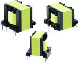
Practical Transformer and Equivalent Circuits
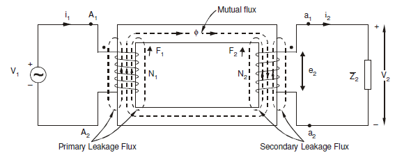
Transformer windings are made mainly of copper. Although copper is a very good conductor, it still has some internal resistance. Hence, both the primary and the secondary winding of a transformer have finite resistances viz. R1 and R2. These resistances spread uniformly throughout the windings and give rise to copper losses (I2R).
Let us consider that the emf I1N1 in the primary winding induces the flux Φl1, the emf I2N2 in the secondary windings, and the leakage flux Φl2. Both the resistances are regarded as the leakage reactance of the transformer windings. They are series effects at very low (50Hz / 60Hz) operating frequencies. These can be regarded as lumped parameters for ease of calculations.
Therefore, the transformer is considered to consist of lumped resistances R1 and R2, and reactance X l1 and X l2 in series with the respective windings. However, the induced emfs E1 and E2 may vary slightly from the secondary voltages V1 and V2 due to the presence of the lumped impedances. This phenomenon is observed due to small voltage drops in the winding resistances R1 and R2 and leakage reactance.
The below equation gives the transformer ratio as:
a= (N1/N2) = (E1/ E2) ≈ (V1 / V2)
Practical or Non-Ideal Transformer
Equivalent Circuit
Now, the excitation current I0‾ can be divided into two components Im‾ and Ii‾. Im‾ is its magnetizing component that creates mutual flux Φ‾, and Ii‾ is the core loss component that provides the loss associated with alternating of the flux. It can be represented as
I0‾ = Im‾ + Ii‾
Here vector form is indicated by the negative (‾) symbol.
Hence, the equivalent circuit of a practical transformer can be represented as shown in the figure below
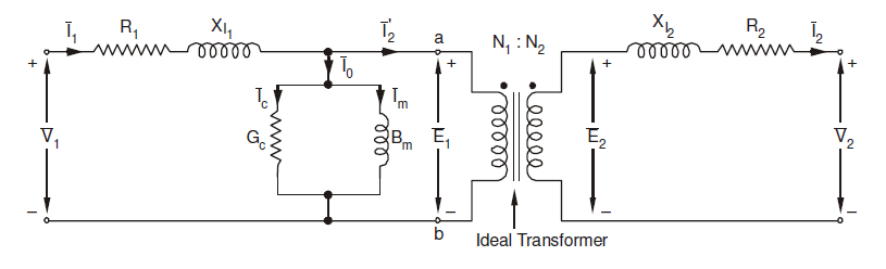
Equivalent Circuit of Transformer
Here,
Gc = conductance
Bm = Susceptance
The impedance can now be referred to the primary side resulting in the following circuit:
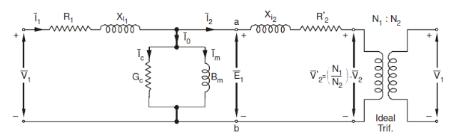
Equivalent circuit referred to primary side is as follows: (core is neglected)
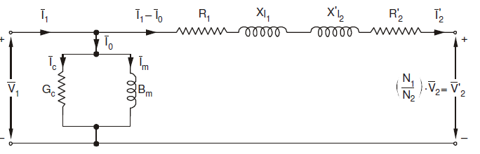
Equivalent circuit referred to primary
X l2’ = (N1/N2)2 X l2
R2’ = (N1/N2)2 R2
The load voltage and currents referred to primary side are:
V2’ = (N1/N2) V2
I2’ = (N1/N2) I2
V1’ = (N1/N2) V1
I1’ = (N1/N2) I1
Gi’= (N1/N2)2 Gi
Bi’= (N1/N2)2 Bi
X l1’ = (N1/N2)2 X l1
R1’ = (N1/N2)2 R1
Phasor Diagram
Applying Kirchhoff's Voltage Law on the primary and secondary side of the equivalent circuits
V1¬=E1+I1R1+jI1X1
V2¬=E2+I2R2+jI2X1
I1=I2’+I0’= I2’+ (Ii + Im)
Using these above equations, the phasor diagram for practical transformer, can be drawn as follows:
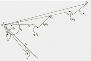
Phasor Diagram for Equivalent Circuit of a Practical Transformer