Transformers are one of the widely used electrical devices around the world. These devices convert higher voltages into lower, thereby making them ideal for household uses. Transformers transfer electrical energy between circuits without altering their frequency. Various types of transformers are used for electrical projects. Although these devices differ in terms of their designs, they all follow a basic principle of Faraday’s Cage. This post discusses one such important variety of transformer – single phase transformer, and its working mechanism.

Basic Introduction to Single Phase Transformer
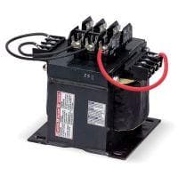
The single phase power transformer is a device, which uses a single-phase AC current. This means the transformer depends on a voltage cycle, which operates in an integrated time phase. These transformers are used for lowering long distance electrical signals into power levels, which are utilized by light-commercial, as well as residential applications.
The change in current is determined by the ratio of primary windings (input) to secondary windings (output). Many single-phase transformers allow adjustable turn ratios, however, others have fixed 1:1 ratio that can be used to isolate circuits.
Highest voltage in single-phase transformers vary as per the industrial regulations and utility infrastructure.
Introduction to Working Principle of Single Phase Transformer
How does a single-phase transformer work? Read below to know more:
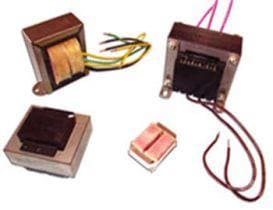
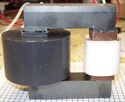
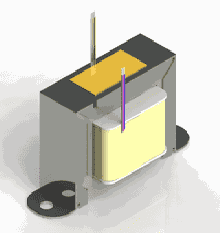
- A single phase transformer comprises primary and secondary windings. These windings feature insulated wires that are wound on a single iron core.
- The primary winding is connected to an AC source, and secondary winding is connected to a load. Iron core links the flux in these both windings.
- The primary winding on energizing produces an electromagnetic field that collapses in the iron core. This electromagnetic field induces power at the load hooked to the secondary winding.
- The collapse and power build up is known as magnetic flux. This flux occurs at six times a second (60 Hz) in an AC circuit.
- The amount of voltage and amperes between the load and the source can be changed by altering windings on the primary and secondary.
- If the voltage is increased by n times than the original transformer value, the current in the secondary coil will reduce to 1/nth the value of the current in primary coil.
- RMS values are calculated as:
Primary induced emf E1 = 4.44 f N1 φm volt
Secondary induced emf E2 = 4.44 f N2 φm volt.
Considerations to Make When Selecting a Single Phase Transformer
While selecting the single phase transformer, you need to consider the following factors:
- Operating Frequency Range
- Primary and Secondary Voltage Rating
- Power Rating
- Secondary Current Rating
- Operating Temperature