PRODUCTS
- High Voltage Transformers
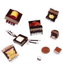
- Switchmode Transformers
- Flyback Transformers
- Trigger Pulse Transformers
- Step Up/Down Transformers
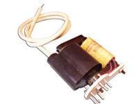
- Power Transformers
- Toroidal Transformers
- Antennas and Air Coils
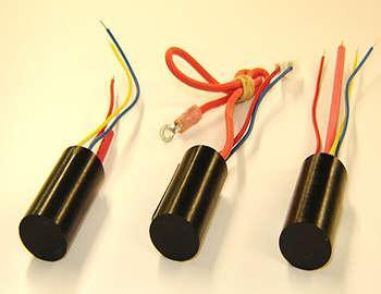
- Down Hole Applications
- DC Igniters
- High Current Inductors
- Custom Manufacturing
- Hydrogen Coils
- Control Transformers
- Inverter Transformers
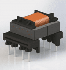
- Low Profile (LPC) Transformers
- Ferrite Transformer
- Pulse Transformers
- Single Phase Transformer
- Specialty Transformers
- Isolation Transformer
- Surface Mount Transformer
- Toroidal Inductor
- Air Core Inductors
- Ferrite Inductors
- Power Inductors
- Surface Mount Inductors
Quick Contact
The Ideal Transformer
Definition of Ideal Transformer
An ideal transformer is often referred to as an imaginary transformer, because it does not have any loss in it. The efficiency of this transformer is considered to be 100%. So, there are no losses (i.e. core losses, copper losses, hysteresis losses, eddy current losses etc.) associated with the operation of an ideal transformer.
Ideal Transformer Model
The model of an ideal transformer is developed by considering a transformer, which does not exhibit any losses. This means that the transformer has purely inductive windings and the transformer core is loss free. Moreover, there is zero leakage reactance associated with the transformer.
In a practical transformer, whenever a low reluctance core is placed inside the transformer windings; the maximum amount of flux passes through the core. However, there will be some flux that will not pass through the core but will pass through the insulation used in the transformer. This flux is called the leakage flux of the transformer because it does not take part in the transformation action of the transformer. In an ideal transformer this leakage flux is also considered to be nil. This means that 100% flux passes through the core and links with both windings of the transformer i.e., primary and secondary.
Both primary and secondary windings are desired to be purely inductive. In the “real world”, both windings have resistance which causes a voltage drop and I2R losses. In an ideal transformer model, the primary and secondary windings are also considered as ideal, which means that the resistance of the winding is zero.
Ideal Transformer
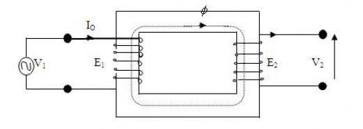
Now, in an ideal transformer if an alternating source voltage V1 is applied in the primary winding; there will be a counter emf E1 induced in the primary winding. Here, E1 is purely 180° in phase opposition with supply voltage V1.
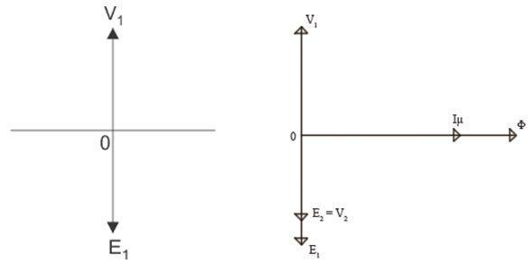
Furthermore, the primary winding draws current from the source to produce a required magnetizing flux to develop a counter emf E1 across it. Since the primary winding is purely inductive, the current (Iμ) at 90° lags from the supply voltage. This current is called magnetizing current of an ideal transformer. This alternating current Iμ produces an alternating magnetizing flux Φ. This flux Φ is proportional to current Iμ, and hence is in phase with it. As the magnetizing flux Φ is also linked with secondary winding through the transformer core, another emf E2 will be induced in the secondary winding. This is called mutually induced emf.
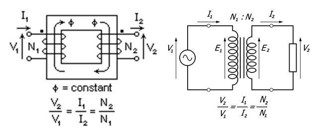
As is depicted in the figure and the equation above the secondary winding is placed on the same core as the primary winding and is purely inductive. Therefore, the emf induced in the secondary winding of the transformer, E2 is in the phase with primary emf E1. However, it is in phase opposition with source voltage V1. Hence, for an ideal transformer, E1I1 = E2I2.
Characteristics of Ideal Transformer
Following are the characteristics of an ideal transformer:
- Zero winding resistance: The resistance of both the primary and secondary winding in an ideal transformer is zero. Both the windings are purely inductive.
- Infinite core permeability: Due to higher core permeability no magnetizing current is required to magnetize the transformer core.
- No leakage flux: In an ideal transformer 100% flux from primary winding gets linked with the secondary.
- 100% efficiency: An ideal transformer does not have any losses. Thus, in an ideal transformer the output power is exactly equal to the input.