PRODUCTS
- High Voltage Transformers
- Switchmode Transformers
- Flyback Transformers
- Trigger Pulse Transformers
- Step Up/Down Transformers
- Power Transformers
- Toroidal Transformers
- Antennas and Air Coils
- Down Hole Applications
- DC Igniters
- High Current Inductors
- Custom Manufacturing
- Hydrogen Coils
- Control Transformers
- Inverter Transformers
- Low Profile (LPC) Transformers
- Ferrite Transformer
- Pulse Transformers
- Single Phase Transformer
- Specialty Transformers
- Isolation Transformer
- Surface Mount Transformer
- Toroidal Inductor
- Air Core Inductors
- Ferrite Inductors
- Power Inductors
- Surface Mount Inductors
Quick Contact

Theory of Operation of Single Phase Transformers
Definition of Transformer
An electrical power transformer is a static device, which transforms electrical energy from one circuit to another without any direct electrical connection. It also performs this with the help of mutual induction between two windings. It can transform power from one circuit to another without changing its frequency, but may be at different voltage levels depending upon the need.
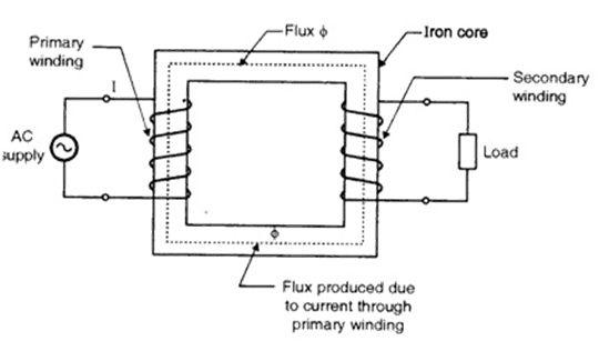
Single Phase Transformer Schematic
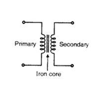
Transformer Symbol
Transformer Construction
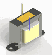
The three main parts of a transformer are:
- Primary Winding: The winding that takes electrical power, and produces magnetic flux when it is connected to an electrical source.
- Magnetic Core: This refers to the magnetic flux produced by the primary winding. The flux passes through a low reluctance path linked with secondary winding creating a closed magnetic circuit.
- Secondary Winding: The winding that provides the desired output voltage due to mutual induction in the transformer.
Working Principle of Single Phase Transformers
The working principle of the single phase transformer is based on the Faraday's law of electromagnetic induction. Basically, mutual induction between two or more windings is responsible for transformation action in an electrical transformer.
Faraday’s Laws of Electromagnetic Induction
According to Faraday’s law, “Rate of change of flux linkage with respect to time is directly proportional to the induced EMF in a conductor or coil”.
Basic Transformer Theory
The primary winding is supplied an alternating electrical source. The alternating current through the primary winding produces an alternating flux that surrounds the winding. Another winding, also known as the secondary winding, is brought close to the primary winding. Eventually, some portion of the flux in the primary will link with the secondary. As this flux is continually changing in amplitude and direction, there is a change in flux linkage in the second winding as well. According to Faraday’s law of electromagnetic induction, an electromotive force (emf) is induced in the secondary winding which is called as induced emf. If the circuit of the secondary winding is closed an induced current will flow through it. This is the simplest form of electrical power transformation; this is the most basic working principle of a transformer.
The principle of operation of a transformer has been explained in the following simple steps:
- As soon as the primary winding is connected to a single–phase supply, an AC current starts flowing through it.
- An alternating flux is produced in the core by the AC primary current.
- The alternating flux gets linked with the secondary winding through the core.
- Now, according to Faraday’s laws of electromagnetic induction this varying flux will induce voltage into the secondary winding.
Related Products
The aforesaid type of transformer is theoretically possible but not practically, because there are losses associated to the operation of transformers.


